"What a refreshingly honest blog about listening to music through hi-fi. So happy to see views based upon the enjoyment of music rather than so-called sound 'quality'." - Peter Comeau, Director of Acoustic Design at Mission / Wharfedale
Showing posts with label DIY. Show all posts

Sunday, 11 February 2024

A "New" Retro Streamer - Pushing the LK Envelope

For information only: this post is not a set of instructions nor is it intended to encourage any kind of modification of electrical products. As they say: "Do not try this at home".

Some of you may have read through the first "episode" of what has now started to be a theme - modernise a Linn LK enclosure with a streamer, or, from the other perspective, taking a modern streamer down the retro route.

That little excursion is available here. It covers off the history of the LK boxes and describes the Sneaky Music DS also used in this project.

A quick recap - that story covers converting an example of the iconic Linn "LK" enclosure into a streamer as purely a source component, using a Linn Sneaky Music DS in "source only" mode.  That's possible in a non-ventilated case, but to use the full features of a Sneaky, including the power amplifiers, that needs a ventilated case, so something from the all-in-one or the power amp sections of the LK range of products.

The other difference is that in the previous project I wanted to present only the source component connections to the outside World, but with this project the intent is to provide all of the Sneaky's connectivity so all of its functions can be enjoyed. Let's see how it panned out..

Basics

Ingredients this time:

- Linn Sneaky Music DS

- Linn LK85 Power Amplifier (with dead mainboard)

- Lots of M3 fasteners

Plan

- Strip the interior out of the LK85

- Trial fit the Sneaky MDS board and PSU

- Work out all the fittings etc., similar to the previous project

Did That Happen?

No. And, yes.

Starting with the LK85, which had a dead mainboard, all the innards were removed - as it happens the LK85 toroidal transformer was repurposed into an LK140 power amp that had a healthy mainboard but a dead transformer.  So the LK140 won't produce the power it used to, but its back up and running and can be used again.

The LK85 chassis stripped bare looks like this:


The back connector panel is at the top of the image, the toroidal transformer mounting hole is midway down on the right then the ventilation and substantial heatsinks.

The ventilation and heatsinking on the LK85 and give confidence that the comparatively low power amps in the Sneaky Music DS will be adequately cooled.  Next it was time to remove the heatsink from the base of the LK chassis - this involves drilling out the securing rivets.

Drilling out the heatsink rivets

This left lots of space to work in side the chassis but also a base plate that wasn't particularly secure.  So once the heatsink was out its mounting holes, that also mate to a centre strengthening plate, were replaced with M3 nuts and countersunk bolts.


Countersunk bolts replacing the heatsink rivets


So that's the basic starting point.  Time to have a look at how to layout the Sneaky boards inside the LK chassis, which is likely to be different to the previous project because there's now the need to look after the power amp and it's heat production.

And then something struck me - once the Sneaky MDS is relieved of its clamshell outer panels, the remaining chassis looked very similar in width to the LK.  If all went well, perhaps the whole Sneaky chassis would slide down into the LK with no modification? A quick check and I found that it is EXACTLY the same width as the LK - so no, it won't slide in easily.  Because the LK box has a chassis with sides and then the top / side panels are a slide over clamshell, the internal side walls are not visible on a fully assembled product. A few measurements told me that it would be possible to cut away sections of the chassis side panels and integrate the entire Sneaky MDS into the LK rear panel - so no need to strip the Sneaky boards / PSU and no need to use jumper cables from those boards to a custom back panel.


Cutting away the side and rear panels ready to accept the Sneaky MDS chassis in its entirety. Around 3/4 of the length of the side panel has been removed.

Trial fitting of the whole Sneaky MDS chassis into the newly cutaway LK inner panels.

In the above picture you can see that the external width of the Sneak MDS is exactly the same width as the LK chassis and in this trial fit, this was confirmed.  The 4x threaded bosses in the top of Sneaky chassis are the mountings for the external clamshell panel.  They are replicated on the underside and their positioning means that only 4x standoffs can be mated to them to supply support and fixing in to the LK. Plus the height up from the LK base means no need to powerfile away the LK's old threaded bosses, so one less job to do.
I didn't have standoffs of quite the right length to screw directly into the Sneaky chassis, but adding an nut to the threaded section before mating them up gave exactly the right clearance.

Making the standoffs in stock a couple of millimetres taller

Threaded standoffs fitted into the Sneaky threaded bosses that normally provide a fixing point for the outer clamshell panels

Underside of the Sneaky chassis with standoffs in place


4x holes were drilled to align in the LK chassis and another trial fitting undertaken. Note that the front to back location of the Sneaky chassis aligned the original back panels of both products.

Alignment of the remains of the LK rear panel (along the bottom of the picture) with the entirety of the unmodified Sneaky rear panel. Together they don't vertically add up to the same total of the old LK back panel, leaving a gap across the whole width

The only modifications needed to the Sneaky are two fold.  First, and easiest to describe, is swapping the original front blue panel LED to the green "power" LED next to the on-off switch of the LK.  This just involved a swap of the connector (as per the previous project) and re-routing of the cable.  The second part was to accommodate using the front power switch.  This required a slight tweak - the brown positive cable from the IEC rear panel socket that goes directly to the PSU was unsoldered and effectively routed round to the power switch on the front before going back to the PSU. Handily, by fitting a rubber grommet around the Sneaky's front LED mounting hole, it was possible to route this cable without and modifications to the Sneaky chassis.

The LK power switch assembly as removed from the amp.  The IEC socket is cut off leaving the 2x brown cables going to the switch

This is the Sneaky front LED mounting point.  A rubber grommet protects cables passing through - this was used for the mains switch cable and the LK green front panel LED

Front panel switch fitted with a 2 pin connector

The redirected brown cable is sleeved and makes its way neatly under the PSU output cable off to the front panel power switch


Passing out of the Sneaky chassis to the front panel

Adding a 2 pin connector to mate up with the connector added to the front panel switch leads


And that's about it. Except for that gap across the top of the rear panel.  The material for this was taken from the top of the original LK back panel, but mounting needed to be resolved.  Handily some offcuts of aluminium panel from the last project were just the right width to create a pair of mounting brackets.  These were cut to length, bent to shape and bonded to the back panel gap filler. They then sit neatly onto the Sneaky's upper clamshell mounting points.

Offcuts cut to size for their new role

Offcuts bent into brackets

Bonding the newly fabricated brackets to the newly created back panel filler panel. Note use of universal clamping equipment

And that was largely that.  Some primer and matt black spray paints finished off the exposed LK chassis edges and spruced up the rear panel.  I used satin black on the first of these projects and gave matt black a try here.  I will keep to the satin for future project.


So here it is, the second of the LK streamer projects.  This was a simpler build than the previous one and is probably the route I'd use again in the future.  It has the benefit of exposing all the functions of the Sneaky but it has the downsides of needing a vented enclosure (harder to get hold of because the amps are probably mostly still in use) and it doesn't have that more bespoke feel to it. There is one further advantage - the Sneaky needs the absolute minimum of changes, so could be converted back to standard in about 15 minutes.

Rear filler panel mounts


Finished
LED and mains switch cables pass through the grommeted LED hole of the Sneaky. Connector of the power switch cable

A neat final result

Base panel labelled up with the new information.  LK mains transformer mounting hole plugged with a rubber bung

As per the plan - absolutely no clue that this is anything other than an LK power amplifier

Until you turn it around and find a whole bunch of unexpected connectors.  As you can see in this picture the top filler panel, the unmodified Sneaky back panel and the remaining lower edge of the LK back panel marry up well to make an (almost) seamless result.

And finally...

Here is the Sneaky going through its boot up sequence, using the original green LK LED rather than its own blue LED.


Tuesday, 26 May 2020

Building a Nindex Speaker - Part 3 Crossover Design, Measurements and Listening

PART 1 OF 3 HERE
PART 2 OF 3 HERE

As explained back in Part 1, the speaker is intended only to be operated in active mode with a Linn Exakt system. So a bit of an explanation of Exakt first.

In a traditional hifi system, an amplifier feeds a full range signal to the back of the speaker cabinet, then a passive electrical system inside the cabinet (the crossover) splits the signal into the correct frequency ranges for each of the drive units to handle.  This crossover is made of high power components which sap power from the signal, have wide tolerances and introduce their own problems such as phase errors.
In Linn Exakt, the full range signal from a digital source is fed to a component called an Exaktbox. In here the signal is split into the frequency range appropriate to each driver in the digital domain - this means it is done far more accurately than can be achieved in the speaker's own passive analogue crossover. The Exakt system allocates a DAC (digital to analogue converter) to each speaker driver and then the signal is passed to a power amplifer for each driver.  This is then connected directly to the appopriate driver in the speaker cabinet without any further components getting in the way, so the amp has better control over the movement of the driver.
So Exakt has very precise control over what gets to each driver and it introduces no phase errors of its own.  In addition to this, the system corrects for any phase errors within each driver and any frequency response "features" of the driver by applying an opposite signal to the error. Finally it also introduces time delays to drivers that are closer to the listener, in order to better time align the sound getting to the listener's ears. Some information here plus if you Google Linn Exakt you'll get lots more information and opinion.
Personally, I call it Linn Lessinexakt, but I don't suppose that would go down well in the marketing department...

Digital Design

As a consequency of the Linn Exakt approach, the Exaktbox system can be programmed to address pretty much any loudspeaker available, as long as there is someone who can measure the speakers and then carry out the design work to be loaded to the Exaktbox.  This is the service I offer under the SpeakerFilters brand.

There are several stages involved in creating the filters:
  • Physical measurement of the speakers which are then uploaded to Linn's database
  • Acoustic measurement of the passive speaker prior to modification to get a view on its existing characteristics (not part of this design work as there's no existing passive design to measure)
  • Electrical measurement of the speaker drive units (in and out of the cabinet if a ported design)
  • Translation of the electrical measurements into the parameters expected by the Linn Exakt Design system
  • Creation of initial crossover points and slopes, along with approximate attenuation of individual drivers - usually based on the passive crossover design
  • Acoustic measurement and listening with lots of experimentation to get the right mix of measured results and the best listening experience - this is the most time consuming with lots of iterations
So these were the next steps to the project.

Electrical Measurements

These are based on pretty straightforward impedance sweeps - showing the impedance in relation to the input frequency range from 20Hz to 20kHz - the generally accepted range of human hearing.

An example of the bass driver in the Nindex project is shown below:


The upper (red) line shows the phase response of the driver, the lower (blue) line shows the impedance curve which is fairly typical of a driver in a sealed cabinet - the peak is the driver's resonance frequency when mounted in the cabinet. By analysing various elements of this trace, the "thiel-small" parameters for the driver can be derived and fed into the Exakt design tools.

Looking at the response curves of the TM1-A array, it was a fairly straightforward choice of where to start with for the crossover points:

Mid Range Dome Frequency response - shows that the crossover points need to be above 850Hz at the lower end and below about 7500Hz at the top end (when the off-axis response starts to fall away)

The tweeter has a very wide response range and looks like it could handle from 1500Hz or so upwards - so it would be a good design to use with a larger mid-bass in a two way system.

I started with nominal crossover points of 1500Hz and 7000Hz, both with Butterworth 4th order crossovers - for those of you concerned about such steep slopes, remember that, unlike a passive crossover, the Exakt digital crossover doesn't introduce phase distortions based on the steepness of the slope. So the slope can be adjusted to suit integration requirements and the subjective listening experience.

The first acoustic measurement to take is just a quick sweep to check if the relative volumes of the drivers are somewhere near close.  Using the bass driver with attenuation of 0dB I usually put in -3dB for a mid-range and -4dB as the starting point.  Then work from there, usually by ear first, then refining with acoustic measurement. Its possible to hear changes of as little as 0.1dB which most people find very surprising until they hear it for themselves.

Then starts the refining of the crossover points - but only one at a time of course - listening for where the instruments sound more believeable but most importantly where the music itself is more engaging plus best for the most stable central imaging but widest overall spread of image - its not scientific, other than staying within the sensible ranges for each driver.  A crossover point is a nominal value - once this seems about right, more listening is done to various combinations of each driver roll-off point and therefore which mix is right and how steep the slopes might be.  For the bass to mid crossover, its easy enough to hear changes of around 25Hz in the values.  For mid to tweeter, I usually work in chunks of 100Hz.

Design work was completed using a Linn Majik DSM/3 network streamer / pre-amp and a Linn Majik Exaktbox-i which combines 8 channels of Exakt processing, 8 DACs and 8 power amplifiers - a remarkable bit of kit all in one box. The Exaktbox is the pre-Katalyst DAC version (at time of writing and design work - the upgrade is planned for the future).

Linn Majik DSM/3

Linn Majik Exaktbox-i


Here's the data that I ended up with for the Nindex:

Bass Driver
  • Roll-on = 10Hz
  • Slope Type = Butterworth
  • Slope Gradient = 4th Order
  • Roll-off = 1100Hz
  • Slope Type = Butterworth
  • Slope Gradient = 3rd Order
  • Attenuation = 0dB
  • Time Alignment = 0
Mid Driver
  • Roll-on =  1600Hz
  • Slope Type = Butterworth
  • Slope Gradient = 3rd Order
  • Attenuation = 4.0dB
  • Time Alignment = -119 microseconds
  • Roll-off = 4800Hz
  • Slope Type = Butterworth
  • Slope Gradient = 3rd Order
Treble Driver
  • Roll-on =  6700Hz
  • Slope Type = Butterworth
  • Slope Gradient = 3rd Order
  • Attenuation = 9.1dB
  • Time Alignment = -87 microseconds
  • Roll-off = 28000Hz
  • Slope Gradient = 4th Order
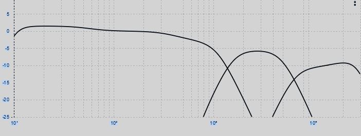
In the simplest terms, the resulting graphic looks like this below. Note that this is the electrical output required to achieve the crossover points and a flat response from each drive - so the curves aren't straightforward because Exakt is allowing for the characteristics of the drivers themselves.  Plus, in this image there are actually some filters hidden from view but having an effect - for example there is a small lift below 60Hz to add a little bit of weight to the bass.

The electrical outputs to achieve the crossover points

I then, by habit, add some "protective" filters to each driver - they're not shown above, but I'll put in a low pass filter for the bass driver than allows frequencies between 0Hz and 3000Hz. For the tweeter, for example, I'll add a high pass filter from 3000Hz upwards.  For example for the bass:

Example "safety" filter for the bass driver
Baffle step is a phenonmenon that means when a certain frequency and above reaches the edge of the baffle, it diffracts and becomes amplified for the listener - this is often cited as the reason that studio monitors are built into walls, to avoid any edges. This is obviously not possible for a speaker designed in a box so its best to put in step filters at the frequencies calculated on the baffle width and height.  So those calculations are done and appropriate filters added - with attenuation levels that are guessed to start with (they're often of a similar value between designs with the size of the attenuation rising as the frequency rises) and are typically in the range 0.2 to 2.5dB.  I usually start the step curve a little before the intended frequency and keep the slopes at a nice and gentle 2nd order. Here's the step for the mid driver which kicks in about 15Hz before the calculated point and is attenuated by 1.5dB:

Mid Range Baffle Step Filter
At this point, for confirmation of the rough acoustic measurements and subjective work, I'll take an acoustic 20 to 20000Hz sweep to make sure there are no glaring errors - preferring to work this way rather than relying entirely on measurements.

So now we have a pretty flat response through the design process, a choice of crossover points that give the best subjective sound and imaging.  Of course, in the background of all this the Exakt system has applied the calculations to each driver to deliver minimum phase errors, but all of that is invisible to the designer.

Now its time to do some detailed acoustic measurements and iron out any signficant frequency response anomylies in the drivers themselves.

I use REW software for acoustic measurements, paired with a calibrated UMIK-1 microphone connected to the laptop by USB. The laptop is dedicated to only the audio work, runs Windows 7 and pretty much nothing else. No fancy audio programmes nor drivers or anything else that will potentially add noise or unwanted processing effects.  For design work I always measure the speaker on-axis vertically with the tweeter as that is usually the most directional driver.  Horizontally I will measure on-axis and 30 degrees off axis.

My intention with this design was to get the 30 degrees off-axis frequency response pretty close to flat.  This will mean that on-axis the speaker will sound a little "bright" in that the treble output will be higher than the rest of the audio range.  This is deliberate to allow the speaker to be pretty much optimal with just a very small amount of toe-in.  Then for those who like a little more brightness or for older listeners whose hearing is starting to tail-off at the higher frequencies, a little more toe-in of the speaker will bring that change in balance.

Measurements are taken at 300mm to allow the mic to pick up the full frequency range but to minimise the effects of room reflections.  Not having an anechoic chamber to work with means that measurements below about 110Hz need to be completely ignored as they are prone to standing waves in the room.  Any tweaking below 110Hz is done purely by ear.


The camera angle makes this look more, but this is measuring 30 degrees off-axis in the horizontal

The software provides a sweep from 20 to 20,000Hz and measures the output from the speaker, corrected for the calibration of the microphone. I ignore all readings below 110Hz.

This then gives a picture of any interesting "features" of the frequency response of the drivers themselves, and, if there are any, where the drivers are perhaps overlapping too much, or leaving a trough due to not enough overlap.  Usually some quick adjustments to crossover points or possibly slopes get this sorted quickly.  The "features" of the drivers can be adjusted for with the Exakt digital crossover designs.

This is done by "modelling" the humps and dips in the response curve, then Exakt compensates electrically by applying the inverse to the signal delivered to the speaker.  So a 3dB hump at 1000Hz in the speaker will have an exact opposite - 3dB output applied at 1000kHz. It is possible to add bell curves, high or low pass and shelves. The height and width of a bell curve is adjustable.  It is possible to model each left and right speaker individually, or just go with a blend of the average of both.  In this project I worked on individual drivers - in commercial models it makes more sense to go with an average as there is little sense in trying to second guess the features of individual products out in the market.

So here is the resulting modelling for the left speaker with all the humps and dips modelled in for Exakt to correct for. It has to be said, apart from the need to add a lift from about 16000Hz upwards, the tweeter was the best behaved of the drivers.  Please be aware that I don't spend days and days dialling out every single ripple in the response curve. It would be rather unproductive - I focus on the main features and leave it at that.

The top line is the modelling of the "features" in the frequency response of the drive units.  The bottom 3 lines are the phase characteristics that Exakt has calcuated for correction.  Note, at this point the features include the effect of the cabinet, not just the drive units, so some of these could be due to the cabinet resonances mentioned in the build section (Part 2).

Top is the modelling of the frequency response of the drive units, including their "features".  The bottom is the Exakt modelling of the phase characteristics for correction

RESULT

So what is the ouput of all that work?

I've used 1/12th smoothing of the acoustic measurements to give a realistic idea of the reponse curve.  Below are 2 graphs to show why I'm mentioning this - if I was a speaker manufacturer, I would be tempted to publish the the 1/3th smoothing to make it look miraculously good!

Remember to ignore everything below 110Hz as there is too much room interaction.

Example with 1/3 Smoothing. Contrast With 1/12th Below. See how the above pretty much eliminates the room iteraction!  And those who really like their hifi to be "objectivist" rather than "subjectivist" sometimes forget that the numbers can be manipulated.  This is exactly the same data, just presented differently!

Exactly the Same Measurement But with 1/12th Smoothing - I use 1/12th in the results below
Single speaker result below - remember it is designed to be listened to off-axis.  Here you can see the more pronounced upper frequencies that would result in pointing the speakers directly at the listener compared to the intended only slight toe-in. Rotating the speakers with more toe-in allow a slightly brighter presentation if required.

Green line is on-axis response measurement. Red line is 30 degrees horizontal off-axis response measurement
 A word about phase correction with Exakt - one of its key selling points. It must be said that it is a phase error minimisation solution, it doesn't deliver a completely flat phase response.  However, I will provide a not to be named phase response example from a very well known domestic speaker maufacturer for comparison.  This is from their £16,000 speaker.  As usual, please ignore the measurements below 110Hz.  I do not post this comparison here to try and claim my project gets even close to being within sniffing distance of having a hint of the performance of the comparison speaker, but just to illustrate the effect of having no phase errors introduced by the crossover and the correction of phase errors within the drivers.

Nindex phase response, 30 degrees horizontal off-axis:
Phase Response of the Nindex Project Speaker

The dotted line in the above graph is the phase response of the £16k speaker
SOUND

So how does it sound?  Well, I'm not at all disappointed by the result. In fact, its rather enjoyable.  I don't think its the most dynamic speaker ever, but it does have a nice sense of flow - its definitely of the more laid back variety.  If you like most JBLs, you'll not like these.  Bass is tuneful but not "kicking", doesn't go massively deep but its pretty good for a box of this size.  There's no real noticable box artefacts, the treble is sweet and very detailed, the mids and vocals a touch polite but well articulated. Maybe it will appeal to those who prefer the BBC type of design?
Perhaps, at the next but one Wigwam Show (plans are already in place for the next one) you'll get a chance to come along for a listen.
Now perhaps its time to hook them up to the Akurate Katalyst / Lejonklou power amps in the main system and see how they get on.  Perhaps there'll be a post script later.

Finally, what's in a name. Well, not much thinking really. The base cabinet is an Index, but they're no longer Index, so they're Nindex. It works with the NINka drivers too. Kind of.

A few parting photos.  Thanks for reading!


PART 1 OF 3 HERE
PART 2 OF 3 HERE

Monday, 25 May 2020

Building a Nindex Speaker - Part 2 The Build

PART 1 OF 3 HERE
PART 3 OF 3 HERE

The choice of drivers and the basic layout having been decided, time to cut holes in the scrap pine as practice with the router is required - this project is the first time I've ever used a router.  Plus, it will give some ideas about what the 2 dome array will look like once in the baffle as there's a need to then design a chamber to cover the rear of the array from the bass driver's energy inside the cabinet.  Another couple of elements I wanted to cover - getting the baffle thicker than standard in most commercial speakers (18mm) but without the huge left over material there would be if I purchased a complete sheet of 25mm mdf - and my idea about "through bolting" the baffle to the rear panel of the cabinet.

I haven't mentioned crossover requirements as yet, because they're not important until the end of the build - I'll be using Linn's digital Exakt crossover system to develop digital filters, meaning no need for a traditional passive crossover inside the speaker. It makes a 3-way easier to design as their passive crossovers are usually very complex, but no need to worry about that here.

So this is where we are:

Former Linn Index II cabinet, with the baffle removed
Linn 040/2 bass drivers
HiVi TM1A dual dome mid / treble array
Thicker front baffle
Through-bolt design from front baffle to rear panel
Infinite baffle design (no port)
Internal chamber to protect the treble and mid drivers from internal bass energy
Linn Exakt digital crossover and actively driven only
Visually, I've decided to just spray paint the new baffle, to keep it simple

Here's a side view of the relative positioning of the drivers:


Here's the first baffle with cutouts, then trial fitting to the cabinet.  The only significant change from this practice attempt was the position of the mid-bass driver.  It was moved up on the baffle to give better alignment with the array but also to move the lower mounting bolts to better clear the inner strengthening board to allow for the through bolts to the back panel. Due to the thinness of this practice baffle, it wasn't possible to rebate the bass driver enough to allow the fitting of the rubber trim ring from the Ninka - something that was fixed in the final baffle design.


Everything just resting in place - no fixings at this point


Trial fixings with stainless steel bolts. This picture prompted the decision to find some black finished dome headed allen bolts
Final Baffle Build

The baffle isn't thick enough for a few reasons - the bass driver needs to be rebated more to allow for the rubber trim ring, its not really rigid enough as there's a lot of material removed to allow the driver install and the thickness of the material where the drivers mount mean it looks unlikely to be strong enough to support through bolting the chassis without the material tearing away.

In order to solve the above, but to avoid buying a full sheet of 25mm, I bought a half sheet of 12 mm mdf with the idea of sandwiching 2 layers together. If I was in the marketing department of a loudspeaker manufacturer, I might describe this design feature as "a multi-layer resin damped rigid absorption system" or something. But really its just 2 layers of mdf glued together...

So then the routing plan was somewhat more complex with the outer front layer of the baffle needing different machining to the inner layer.

Pictures of routing both baffle panels:


Perhaps choosing the complex shape of the combined tweeter - mid range wasn't the best idea for the first router project


The "outer" front baffle - here the holes are big enough for the bass driver and trim ring, but nothing to mount it on - that comes with the "inner" front baffle layer


The back edge of the inner baffle panel was chamfered to help smooth the airflow inside the cabinet.  Not chamfered all the way around though, need to leave strength for the mounting bolts.


Internal Chamber

With a tweeter, its normal just to make sure that the rear of the driver is protected from the internal energy of the bass driver inside the cabinet and its usually just a sealed moulding on the back of the driver that achieves this. Of course, much more expensive designs such as the B&W diamond series or the PMC Finestra go to a lot of effort to deal with radition from the rear of the tweeter with some very fancy cabinet design work. In case you hadn't noticed yet, this isn't a fancy nor expensive design...
With a traditional cone driver, a mid would need a sensibly sized enclosure.  But with a dome driver, it would seem to be best to treat it like the dome tweeter and just protect it from the energy of the bass driver.
Even with the double layered baffle adding up to 24mm, the 2 dome array still protruded into the inner cabinet space.  So it wasn't possible to just fit a covering board to protect from internal energy, but to use something thicker and machine an inner cavity into the material.  Also needed is a way of passing the mounting bolts and cables through whilst maintaining an airtight seal.

So my routing skills pushed further and resulted in probably the messiest part of the build, but at least its not visible on the completed speaker.  Here is the machined chamber:

The pretty rough machining of the internal chamber - rubber grommets for the cables to pass through. Later they'll have silicone sealant added to give a much more effective seal

The back, or inner, face of the chamber behind the 2 dome array
Glue ready to accept the inner chamber panel.  The notches in the main baffle are to allow for the cables to get to the terminals which are located on each side of the drivers

Gluing the baffle layers and the internal chamber.


Completed inner chamber

Here you can see the edge chamfering of the front baffle panel

Bolting

The idea for mounting the baffle was to use 4 of the driver mounting bolts to through-bolt to the rear panel to locate the baffle but also to add rigidity to the whole structure.  The original idea was just to use M4 stainless steel threaded rods.  But visually, I didn't like this idea, as it means nuts on the front rather than bolt heads.  So I added female threaded hexagonal nuts to the back of the 4 mounting bolts which couple the bolt to the threaded rod. Locknuts prevent the rods coming loose from the bolts.  The remaining 6 driver mountings rely upon M4 bolts into captive nuts.  This means the all the drivers and bolts need to be mounted prior to fitting the whole assembly to the cabinet.

Through bolting of the 2 lower bass driver mounts and the middle pair of the array mounts


Captive nuts

Captive nuts at the top, female threaded hex nuts

Mounting points for the bass driver - captive nuts at the top, female hex nuts for the threaded rods a the bottom


Trial fit of drivers into the baffle, including the female threaded hex nuts and using the black painted dome head allen bolts

Trial fitting of the through bolts. Large washers spread the load.  Note the additional pair of bolts and washers used to blank the excess number of binding post holes


Internal Damping, Anti-vibration and Connections

More pseudo-science here, based on nothing more than seeing inside of other speaker designs and a little bit from the portable project I put together some years back.

All panels have a natural resonance frequency.  This can manifest itsself as peaks and troughs in the frequency response of a speaker and often is described by reviewers as a "boxy" sound. So would it be a good idea to add damping material to counteract this? Possibly - the cabinet walls are pretty thin, so I gave it a go. As with the portable project, I've used self-adhesive panel damping from the car industry. But if I treat all the panels the same (for example the side panels probably have identical resonance frequencies as each other) then it will just move the resonance frequency to a different value but still adding each other together to up the output levels of that particular frequency. So, rather unscientifically and purely based on a dodgy theory, the opposite panels were treated with differing sized pieces of damping - hopefully meaning the resonance frequencies are spread out more and therefore less intrusive. Maybe.

I've also seen fairly dense foam used on back panels in a number of speakers - presumably to absorb some energy or disperse standing waves. So a layer of that is added to the back panel of the cabinet.

The silver material is the self-adhesive dampening material.


Below you can see the inside end of the binding posts - as there are now 3 drivers rather than the original 2, 6 terminals are required. You can also see the dense foam on the back panel


Above you can see the inner ends of the connection terminals - they have be upcycled from a pair of Linn 104 speakers that had some faulty drivers and that have contributed to another project underway.

For the chamber at the back of the 2 dome array, an arrangement of small chunks of foam are added - to either absorb any energy coming from the backs of the domes, or to help with protecting them from the bass energy in the cabinet, or a bit of both.  Again, the science may be a bit less than robust.

Damping foam in the 2 dome array inner chamber - first attempt

Second attempt with better shaping and room for the cables

Gasketty

A good seal between drivers and baffle is essential to a sealed infinite baffle design such as this. So some sheets of fishing fly material were obtained - its essentially a very thin sheet of dense foam.  Quite delicate though, so care is needed in handling and cutting.

Card templates were made and trial fitted before cutting the actual material.

Creating the bass driver gaskets

Creating the array gaskets

An array gasket - this was the first attempt. Attempts 2 and 3 were much better, but I didn't take photos
Trial fitting the array gasket


Bass driver gasket in place
A further gasket was put together around the perimeter of the cabinet to seal against the front baffle.


First Trial Build

A few lessons were learned along the way during the trial build.  For example, the spade terminal cable connections on the back of the array had to go and be replaced by soldering the cables directly - there wasn't clearance for the spades.
Also, it became pretty clear why through bolting might not be popular with manufacturers.  Putting aside that it might not be a particularly sound mechanical approach, getting the bolts through the internal wadding of the cabinet, aligned into the holes in the back panel and then getting the baffle lined up with the cabinet is, what could be called "a bit of a faff" and very time consuming.

Originally the array cables were fitted with spades, but these were soon swapped to soldered connections due to restricted space.


The cables have to be connected before threading the bolts through to the back panel. In the final build step the rubber grommets havea silicone sealant added to make them fully effective

 In the above image you can see the initial polyester wadding in the cabinet - this is re-using the quantity from the original Index II.  It turned out to be in adequate in the first listening tests, resulting in a some what loose overblown bass sound.  Later the entire internal space was filled with rolled wadding. A huge improvement in the sound - shown below.

Here the painting of the front edge of the main cabinet can be seen - required because of the construction method - this edge can be seen from a side view of the cabinet.  Also visible here is the baffle sealing gasket (stapled in place, just for alignment purposes).  The final quantity of wadding can also be seen.


First trial build completed

At last, after 9 months of elapsed time, a pair of speakers are ready to test

Here you can see the through-bolt approach.  The extra length does help with assembly to get the bolts to thread through the back panel. Once the project is complete, they'll be cut down to a more sensible length. Also the ex-Linn 104 binding posts can be seen

 
It's taken a while...


Finishing Off

Initial measurements were taken and Exakt crossovers designed, but there was an issue with a loose overblown bass. From some work I did on my "portable" project, I knew this was down to the volume of wadding inside the cabinet, so a partial dismantling took place and more wadding added.  This means re-measuring the electrical characteristics of the bass speakers and re-listening.  It had done the job nicely.

To finish off the front edge of the main cabinet was treated to primer paint and then the baffles sanded with 400, then 800 grit papers.  Three more layers of spray primer, another 800 rub down, 2 more layers of primer and a 1000 grit rub down. Then two layers of matt black spray paint, 1000 grit and 2 more layers of black.
I think a lot more time could've been put into getting a better finish - particularly on the edges.  Maybe some epoxy filler before sanding would have helped. The machined mdf edges are still a bit rought. But they're not meant to be for sale so these some elements, for me, are less important than the resulting sound.


A completed baffle, including the rubber trim ring for the bass driver

Here you can see the extra wadding inside the cabinet - now packed quite tightly. Also the black painting of the exposed chipboard on the front cabinet edge and the baffle to cabinet gasket


Happy enough with the result


PART 3 OF 3 HERE