Part Two Of A Three Part Review
EDITED 30 September 2016: The official Linn conversion kit for the PMCs are now available from Linn dealers - there's now no need to convert DIY as per the described below - although the official kit still requires much of the same actions :) Note that the PMC warranty will still be voided by the Linn kit.
After conversations with Linn about the timing of the conversion kit launch which is still not clear, back in April it was time to take the plunge. So here's what is involved in the conversion from standard Twenty.26 to an Exakt compatible version. To be fair, this conversion could be done for any project to convert the PMCs to any form of active operation, it is not specific to Exakt.
FIRST AND MOST IMPORTANT: THIS CONVERSION WAS DIY AND IS NOT APPROVED BY LINN NOR BY PMC. THIS CONVERSION WILL INVALIDATE THE WARRANTY ON THE SPEAKERS. THIS IS NOT A COMPREHENSIVE GUIDE, IT IS NOT INTENDED AS A SET OF INSTRUCTIONS. ANY FOLLOWING OF THESE STEPS IS ENTIRELY AT THE RISK OF THE PERSON MAKING THE CONVERSION. THERE MAY BE ERRORS OR STEPS MISSING. NO ACCURACY NOR COMPLETENESS CAN BE IMPLIED. YOU HAVE BEEN WARNED!
The basic principle here is to remove all electronics that sit between the rear terminals and the drive units in the speaker. Fortunately, PMC have provided the .26 with pairs of terminals for each individual driver unit within the speakers. This is intended for bi-amp or tri-amp operation of the speakers, still in passive mode. Exakt needs a direct connection to each drive unit within the speaker, so the 3x pairs helps considerably in this conversion. The latest Twenty5.26 from PMC has reverted to a single pair of terminals and uses a metal panel, so would be considerably more work to convert. The plan was to make the conversion reversible, so making as few modifications as possible whilst still achieving the objective.
Dismantling and Removing The Passive Crossover
 |
| The back panel with the vertical terminal links already removed - this is how the speaker would be used in a tri-amp passive arrangement. Note the textured paint finish on the back panel shows every bit of dust and finger mark, but these are easily removed with a lightly dampened cloth, as you will see in the finished article pictures at the end of the post. |
 |
| The panel is held in place by multiple allen headed countersunk machine screws. They're not particularly tight as they're threaded directly into the MDF of the main cabinet. |
 |
| Once all the allen head screws are removed, the panel can be lifted out. Here, a cloth has been used to support the panel on the speaker's stand without damaging the finish of the stand. The panel is a fairly straightforward piece of machined MDF. The crossover is very substantial and looks to be populated with good quality components. Along the top of the picture the cables go out to the individual drive units - these will need to be connected directly to the speaker's rear terminals to enable Exakt operation. At this point they are kept connected until they can be correctly identified. Here the damping foam for the Advanced Transmission Line can be seen. |
 |
| Fortunately, the drive units for each cable are clearly identified and each cable has a clear + side marker on the cable itsself. Before disconnecting the cables, the treble cable was given a single cable tie as a marker, the mid-range cable 2 cable ties and the bass cable 3 cable ties. This makes them identifiable once they are removed from the passive crossover. Note different gauges of cables used |
 |
| The crossover circuit board is attached to the back panel by 4 crosshead corner screws and the mounting bolts for the 6 terminal posts. Here an 8mm spanner is being used to loosen the terminal post nuts. There are 6 nuts, washers and shakeproof washers to be removed. Note these were only nipped up and not tight - presumably to avoid damage to the circuit board. |
 |
| Once the 6 terminal nuts were removed, the corner crosshead screws were removed |
 |
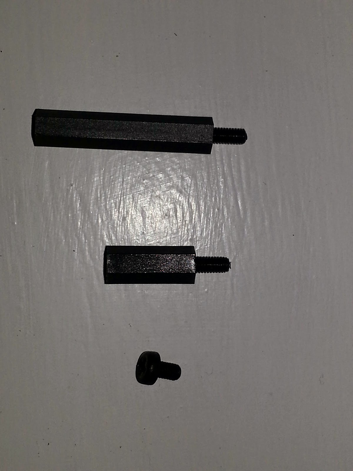
| The crossover board then just lifts off the terminals. Here the plastic spacers that keep the crossover board supported away from the back panel can be seen. This is all the dismantling completed - the posts and spacers all remain in place as this is where the cables that go to the individual drive units will need to be connected |
Conversion
At this point, all the passive crossover components have been removed. The speaker cables that go from the passive crossover to the drivers have female spade terminals, but they now need to be connected to the back of the cylindrical terminal posts. It would be easy enough to just cut off the female spades and solder on some loop terminals, but that would make the conversion back to standard passive more complex and that was something that was to be kept as straightforward and as standard as possible. This maintains the future resale value of the speakers as there is a much bigger market for standard passive speakers than there is for Linn Exakt compatible speakers.
So a conversion from cylindrical terminal posts to male spades is required.
Parts required are 5mm gold plated loop terminals (its hard to find any of these. So here, 8mm are used ones and they're a little larger than ideal so stanless steel 5mm washers were also used to help with the fit), male gold plated 6mm spade terminals, some solder and tubes of insulation
 |
| On the left the 6mm male spade, on the right the 8mm loop. Using pliers, the cable grip part of the male spade was gently squeezed together to the point at which it was a tight push fit into the cable tube on the loop terminal |
 |
| Here the male spade has been push fitted into the loop terminal |
 |
| Working through the 12 connectors - 6 for each speaker |
 |
| Using a 45W soldering iron, heat was applied to the interface between the loop terminal and the spade terminal at this end of the loop terminal's cable tube. Only once the flux would melt on the outside top of the loop terminal tube was the solder applied to the joint - this makes sure that all the surfaces are hot enough to receive the solder at the same time and eliminates the chances of dry joints. Soldering is being carried out on a ceramic tile work surface |
 |
| After cooling the male spade on each terminal was bent upwards to approx 45 degrees to assist with connecting to the speakers' internal cables. Later, after fitting the loop terminal to the speaker terminal posts, the loop terminal was also bent upwards by about 20 degrees as other wise it would have been easy to trap the cables between the back panel and the speaker carcass |
 |
| The terminals are then attached to each of the terminals on the inside of the speaker back panel using the stainless steel washers and the shake proof washers and nuts that originally held the crossover to the terminal posts |
 |
| Then insulating soft plastic tubes were added over the male spades. Probably not necessary. Additional pencil markings show which way up the panel goes and which column of terminals is +ve |
 |
| Here the panel is offered back up to the cabinet and the cables connected. You can see the extra bend put into each of the loop terminals to move the cables away from the cabinet. Tweeter to the top pair, mid to the middle pair and bass cables to the lowest pair, using the previously fitted cable ties to ensure correct connection order. Note, the cables are only just long enough to reach the terminals. |
 |
| Once the panel was refitted, a 1.5V AAA battery was used to ensure that the speaker cones all moved in the correct direction. Put the positive of the battery onto the positive of the speaker and negative to negative and the speaker cone should move outwards, Just a brief touch is enough to check but doesn't damage the drivers |
 |
| The back panel was then masked up to create guides for adding a set of old Linn active system labels |
 |
| Labels installed |

So that was it, all done. Checked, checked and checked again. The connection sequence was as follows:
- Connect bass amp to bass terminals
- Play music quietly and ensure only bass info was coming out of bass drivers.
- Switch off amps
- Connect mid amp to mid terminals
- Play music quietly and ensure mid information is coming out of mid drivers
- Switch off amps
- Connect treble amp to treble terminals
- Play music quietly and ensure treble information is coming out of treble drivers
Enjoy the music. Pack the passive crossovers carefully in bubble wrap and a strong box and store in cool dry place.
Part Three Of The Review Is Here
EDITED 30 September 2016: The official Linn conversion kit for the PMCs are now available from Linn dealers - there's now no need to convert DIY as per the instructions below - although the official kit still requires much of the same actions :) Note that the PMC warranty will still be voided by the Linn kit.


.jpg)