PART 3 OF 3 HERE
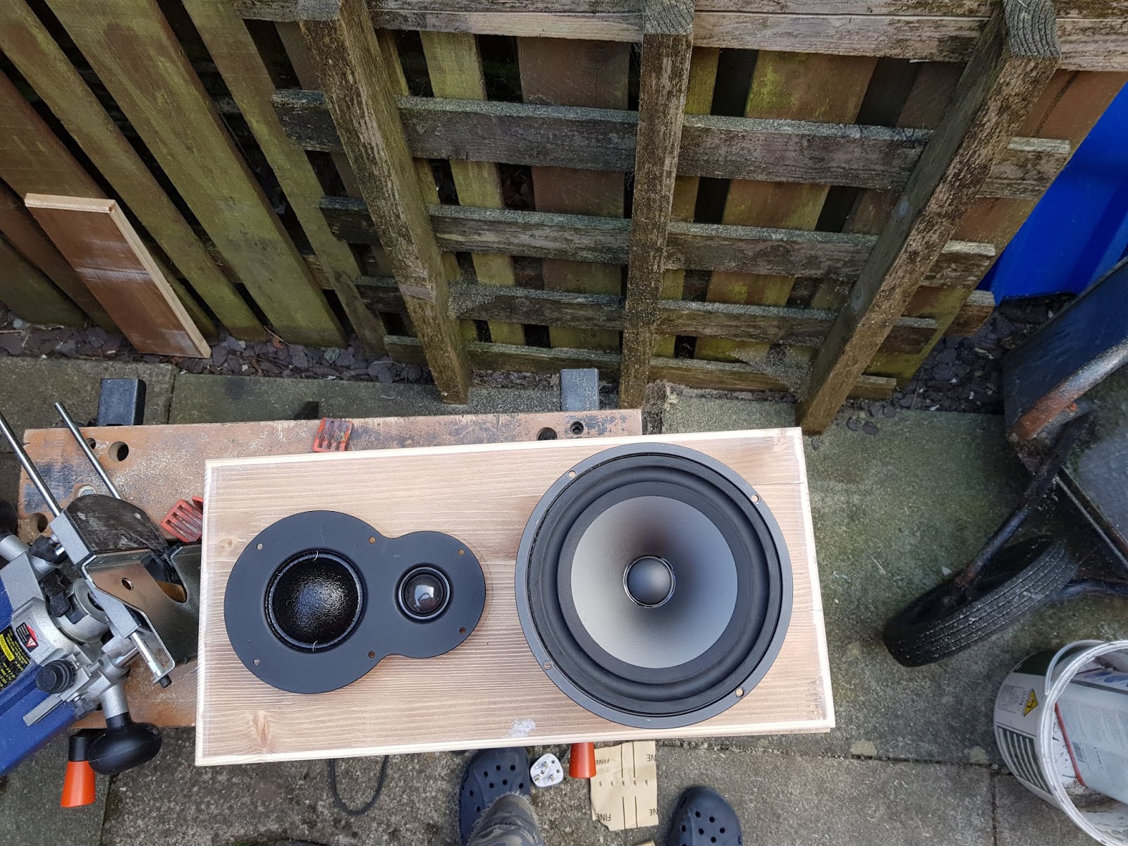
The choice of drivers and the basic layout having been decided, time to cut holes in the scrap pine as practice with the router is required - this project is the first time I've ever used a router. Plus, it will give some ideas about what the 2 dome array will look like once in the baffle as there's a need to then design a chamber to cover the rear of the array from the bass driver's energy inside the cabinet. Another couple of elements I wanted to cover - getting the baffle thicker than standard in most commercial speakers (18mm) but without the huge left over material there would be if I purchased a complete sheet of 25mm mdf - and my idea about "through bolting" the baffle to the rear panel of the cabinet.
I haven't mentioned crossover requirements as yet, because they're not important until the end of the build - I'll be using Linn's digital Exakt crossover system to develop digital filters, meaning no need for a traditional passive crossover inside the speaker. It makes a 3-way easier to design as their passive crossovers are usually very complex, but no need to worry about that here.
So this is where we are:
Former Linn Index II cabinet, with the baffle removed
Linn 040/2 bass drivers
HiVi TM1A dual dome mid / treble array
Thicker front baffle
Through-bolt design from front baffle to rear panel
Infinite baffle design (no port)
Internal chamber to protect the treble and mid drivers from internal bass energy
Linn Exakt digital crossover and actively driven only
Visually, I've decided to just spray paint the new baffle, to keep it simple
Here's a side view of the relative positioning of the drivers:

Here's the first baffle with cutouts, then trial fitting to the cabinet. The only significant change from this practice attempt was the position of the mid-bass driver. It was moved up on the baffle to give better alignment with the array but also to move the lower mounting bolts to better clear the inner strengthening board to allow for the through bolts to the back panel. Due to the thinness of this practice baffle, it wasn't possible to rebate the bass driver enough to allow the fitting of the rubber trim ring from the Ninka - something that was fixed in the final baffle design.

 |
| Everything just resting in place - no fixings at this point |
 |
| Trial fixings with stainless steel bolts. This picture prompted the decision to find some black finished dome headed allen bolts |
The baffle isn't thick enough for a few reasons - the bass driver needs to be rebated more to allow for the rubber trim ring, its not really rigid enough as there's a lot of material removed to allow the driver install and the thickness of the material where the drivers mount mean it looks unlikely to be strong enough to support through bolting the chassis without the material tearing away.
In order to solve the above, but to avoid buying a full sheet of 25mm, I bought a half sheet of 12 mm mdf with the idea of sandwiching 2 layers together. If I was in the marketing department of a loudspeaker manufacturer, I might describe this design feature as "a multi-layer resin damped rigid absorption system" or something. But really its just 2 layers of mdf glued together...
So then the routing plan was somewhat more complex with the outer front layer of the baffle needing different machining to the inner layer.
Pictures of routing both baffle panels:

 |
| Perhaps choosing the complex shape of the combined tweeter - mid range wasn't the best idea for the first router project |

 |
| The "outer" front baffle - here the holes are big enough for the bass driver and trim ring, but nothing to mount it on - that comes with the "inner" front baffle layer |

The back edge of the inner baffle panel was chamfered to help smooth the airflow inside the cabinet. Not chamfered all the way around though, need to leave strength for the mounting bolts.

Internal Chamber
With a tweeter, its normal just to make sure that the rear of the driver is protected from the internal energy of the bass driver inside the cabinet and its usually just a sealed moulding on the back of the driver that achieves this. Of course, much more expensive designs such as the B&W diamond series or the PMC Finestra go to a lot of effort to deal with radition from the rear of the tweeter with some very fancy cabinet design work. In case you hadn't noticed yet, this isn't a fancy nor expensive design...
With a traditional cone driver, a mid would need a sensibly sized enclosure. But with a dome driver, it would seem to be best to treat it like the dome tweeter and just protect it from the energy of the bass driver.
Even with the double layered baffle adding up to 24mm, the 2 dome array still protruded into the inner cabinet space. So it wasn't possible to just fit a covering board to protect from internal energy, but to use something thicker and machine an inner cavity into the material. Also needed is a way of passing the mounting bolts and cables through whilst maintaining an airtight seal.
So my routing skills pushed further and resulted in probably the messiest part of the build, but at least its not visible on the completed speaker. Here is the machined chamber:
 |
| The pretty rough machining of the internal chamber - rubber grommets for the cables to pass through. Later they'll have silicone sealant added to give a much more effective seal |
 |
| The back, or inner, face of the chamber behind the 2 dome array |
 |
| Glue ready to accept the inner chamber panel. The notches in the main baffle are to allow for the cables to get to the terminals which are located on each side of the drivers |
 | |||
| Gluing the baffle layers and the internal chamber. |
 |
| Completed inner chamber |
 |
| Here you can see the edge chamfering of the front baffle panel |
The idea for mounting the baffle was to use 4 of the driver mounting bolts to through-bolt to the rear panel to locate the baffle but also to add rigidity to the whole structure. The original idea was just to use M4 stainless steel threaded rods. But visually, I didn't like this idea, as it means nuts on the front rather than bolt heads. So I added female threaded hexagonal nuts to the back of the 4 mounting bolts which couple the bolt to the threaded rod. Locknuts prevent the rods coming loose from the bolts. The remaining 6 driver mountings rely upon M4 bolts into captive nuts. This means the all the drivers and bolts need to be mounted prior to fitting the whole assembly to the cabinet.
 |
| Through bolting of the 2 lower bass driver mounts and the middle pair of the array mounts |
 |
| Captive nuts |
 |
| Captive nuts at the top, female threaded hex nuts |
 | ||
| Mounting points for the bass driver - captive nuts at the top, female hex nuts for the threaded rods a the bottom |
 |
| Trial fit of drivers into the baffle, including the female threaded hex nuts and using the black painted dome head allen bolts |
 | |||
| Trial fitting of the through bolts. Large washers spread the load. Note the additional pair of bolts and washers used to blank the excess number of binding post holes |
Internal Damping, Anti-vibration and Connections
More pseudo-science here, based on nothing more than seeing inside of other speaker designs and a little bit from the portable project I put together some years back.
All panels have a natural resonance frequency. This can manifest itsself as peaks and troughs in the frequency response of a speaker and often is described by reviewers as a "boxy" sound. So would it be a good idea to add damping material to counteract this? Possibly - the cabinet walls are pretty thin, so I gave it a go. As with the portable project, I've used self-adhesive panel damping from the car industry. But if I treat all the panels the same (for example the side panels probably have identical resonance frequencies as each other) then it will just move the resonance frequency to a different value but still adding each other together to up the output levels of that particular frequency. So, rather unscientifically and purely based on a dodgy theory, the opposite panels were treated with differing sized pieces of damping - hopefully meaning the resonance frequencies are spread out more and therefore less intrusive. Maybe.
I've also seen fairly dense foam used on back panels in a number of speakers - presumably to absorb some energy or disperse standing waves. So a layer of that is added to the back panel of the cabinet.
 |
| The silver material is the self-adhesive dampening material. |

Below you can see the inside end of the binding posts - as there are now 3 drivers rather than the original 2, 6 terminals are required. You can also see the dense foam on the back panel

For the chamber at the back of the 2 dome array, an arrangement of small chunks of foam are added - to either absorb any energy coming from the backs of the domes, or to help with protecting them from the bass energy in the cabinet, or a bit of both. Again, the science may be a bit less than robust.
 |
| Damping foam in the 2 dome array inner chamber - first attempt |
 |
| Second attempt with better shaping and room for the cables |
Gasketty
A good seal between drivers and baffle is essential to a sealed infinite baffle design such as this. So some sheets of fishing fly material were obtained - its essentially a very thin sheet of dense foam. Quite delicate though, so care is needed in handling and cutting.
 |
| Creating the bass driver gaskets |
 |
| Creating the array gaskets |
 |
| An array gasket - this was the first attempt. Attempts 2 and 3 were much better, but I didn't take photos |
 |
| Trial fitting the array gasket |
 |
| Bass driver gasket in place |
First Trial Build
A few lessons were learned along the way during the trial build. For example, the spade terminal cable connections on the back of the array had to go and be replaced by soldering the cables directly - there wasn't clearance for the spades.
Also, it became pretty clear why through bolting might not be popular with manufacturers. Putting aside that it might not be a particularly sound mechanical approach, getting the bolts through the internal wadding of the cabinet, aligned into the holes in the back panel and then getting the baffle lined up with the cabinet is, what could be called "a bit of a faff" and very time consuming.
 |
| Originally the array cables were fitted with spades, but these were soon swapped to soldered connections due to restricted space. |
 | ||
| The cables have to be connected before threading the bolts through to the back panel. In the final build step the rubber grommets havea silicone sealant added to make them fully effective |
 | |
| Here the painting of the front edge of the main cabinet can be seen - required because of the construction method - this edge can be seen from a side view of the cabinet. Also visible here is the baffle sealing gasket (stapled in place, just for alignment purposes). The final quantity of wadding can also be seen. |
 |
| First trial build completed |
 |
| At last, after 9 months of elapsed time, a pair of speakers are ready to test |
 |
| Here you can see the through-bolt approach. The extra length does help with assembly to get the bolts to thread through the back panel. Once the project is complete, they'll be cut down to a more sensible length. Also the ex-Linn 104 binding posts can be seen |
 | ||
| It's taken a while... |
Finishing Off
Initial measurements were taken and Exakt crossovers designed, but there was an issue with a loose overblown bass. From some work I did on my "portable" project, I knew this was down to the volume of wadding inside the cabinet, so a partial dismantling took place and more wadding added. This means re-measuring the electrical characteristics of the bass speakers and re-listening. It had done the job nicely.
To finish off the front edge of the main cabinet was treated to primer paint and then the baffles sanded with 400, then 800 grit papers. Three more layers of spray primer, another 800 rub down, 2 more layers of primer and a 1000 grit rub down. Then two layers of matt black spray paint, 1000 grit and 2 more layers of black.
I think a lot more time could've been put into getting a better finish - particularly on the edges. Maybe some epoxy filler before sanding would have helped. The machined mdf edges are still a bit rought. But they're not meant to be for sale so these some elements, for me, are less important than the resulting sound.

 |
| A completed baffle, including the rubber trim ring for the bass driver |
 |
| Here you can see the extra wadding inside the cabinet - now packed quite tightly. Also the black painting of the exposed chipboard on the front cabinet edge and the baffle to cabinet gasket |

 |
| Happy enough with the result |

PART 3 OF 3 HERE